Tech
10 Gigabit Copper Cable Field Test

10 Gigabit Copper Cable Introduction
10Gbps Ethernet uses the MAC sublayer as defined by IEEE 802.3 to connect to devices such as 10GBase-SR, 10GBase-LX4, 10GBase-CX4, 10GBase-LRM, 10GBase-LR, 10GBase-ER, 10GBase-SW, 10GBase through a 10GB Media Independent Interface (XGMII) -LW, 10GBase-EW and 10GBase-T various physical layer entities.
Among them, 10GBase-T is 10 Gigabit Ethernet for copper medium, and has the following requirements:
(1) Only full-duplex is supported.
(2) Supports point-to-point links and structured cabling topology for star-structured LAN applications.
(3) Support 10Gbps MAC/PLS service interface.
(4) Support for copper cable media in ISO 11801-2002 (specified in detail in clause 55.7).
(5) Supports operation overall transmission distances and grades supported by a 4-pair copper twisted pair with 4 connectors.
(6) Define a single 10Gbps physical layer capable of supporting a 100m 4-pair balanced copper cabling link.
(7) The IEEE 802.3 Ethernet data frame format is maintained on the MAC client service interface.
(8) Keep the minimum and maximum frame lengths specified by the current IEEE 802.3 standard.
(9) Support automatic negotiation.
(10) Meet CISPR/FCC Class A electromagnetic compatibility requirements. The bit error rate of bg(11) is less than or equal to 10^-12 in all transmission distances and grades.
Copper cable media that support 10G include Category 6A Class Ea, Class F, and Class FA. Next, we take the 6A class Ea as an example to talk about the field test of 10G copper cable.
In the field environment, since the test is always carried out after the construction is completed, in the actual wiring system, the certification test of each cable is completed first, and then the alien crosstalk test is carried out.

Test Object Selection
The test objects include the following two:
(1) Insignificant link (Insignificant): The link is low enough to be affected by crosstalk signals and will not affect 10Gbps transmission. The IEC standard considers a link with an alien crosstalk value within the range of 100M~250MHz less than 90dB to be a negligible link, and the standard does not require reporting the test data of a negligible link.
(2) Victim: The cable that is interfered with by the surrounding adjacent links when the test line is crosstalk. After the interfering link is injected with the test signal, the field tester can measure the signal level of the victim link.
When we select the victim link for the crosstalk test, since the signal on the tested interfering link comes from at least 6 groups of interfering links, the on-site test is completed in the shortest time.
Sampling
The following situations can be used as disturbing links (victim links) in cabling engineering:
(1) Select 1% or 5 (the larger value) of the total links with the largest insertion loss (the longest link).
(2) Extract 1% or 5 (the larger value) of the total links with the smallest insertion loss (the shortest link).
(3) Extract 1% or 5 (the larger value) links (medium length links) with medium insertion loss from the total links.
For example, there are 1000 links in the project, 10 longest links, 10 shortest links, and 10 middle links must be selected as the tested links. Each of the above links is tested with a certain number of links selected as sources of interference.
Select all links in the same harness or the link that most closely matches the routing location of the disturbing link. These harnesses may be on patch panels, cross-links, or piping. On the patch panel, select adjacent ports or receptacles as additional links.
When selecting the link under test, the effect of wiring on the patch panel should also be considered. The aggressor link and the interfered link should be in the same path. In this case, the alien crosstalk is more serious.
Choosing a link for testing alien crosstalk is critical and requires some knowledge of cable routing. If you do not know the direction of different links in the building (it is recommended to accurately identify the cable path during construction), since the selected interference source link is not close enough to the interfered link, no obvious crosstalk will occur, and the test results may not be accurate. precise.
Instrument Connection Method
Type A uses only the instrument mainframe, an AXT dual-port adapter and at least two AXT test terminal modules. This setup is only used to test for composite out-of-line near-end crosstalk (PS ANEXT) from the near end of the patch panel cable. Type A testing is used to quickly determine the alien crosstalk environment and can be performed quickly by a single person. Testing with a Type A setup requires connecting the right port of the AXT adapter to the link under test, and the left port of the AXT adapter to the cable that acts as the interfering link. During the test, the right port should always be connected to the link under test, and the left port should be connected to the selected interfering link respectively. The termination module needs to be connected at the far end of the cable from the link under test and the interfering link. The instrument test kit contains 12 terminal modules, and 6 interference links can be selected and connected at one time according to the link under test (the link under test occupies one terminal module), and the terminal position does not need to be changed during the test.
The B-type method needs to use the instrument host and the remote machine, and the AXT dual-port adapter needs at least one AXT terminal module. This setting is used to test the combined extra-line near-end crosstalk (PS ANEXT) and the combined extra-line attenuated crosstalk ratio (PS AACR-F) from the near-end of the link. Type B test is used when the remote ends of the wiring are far apart, and the remote units cannot access the link under test and the interfering link at the same time. To test with the B-type setup, connect the right port of the AXT adapter of the instrument host to the link under test, and the left port to the cable that acts as the interfering link. During the test, the right port should always be connected to the link under test, and the left port should be connected to the selected interfering link respectively. One end of the working area of the link under test is connected to the right port of the AXT adapter on the remote machine of the instrument. The termination module is connected to the far end of the interfering link. A maximum of 12 information sockets can be selected on one side of the work area, the terminal module can be connected at one time, and all tests can be quickly completed on the side of the patch panel.
The C-type method is the most complete alien crosstalk test, which requires the use of the instrument host and the remote unit, and the AXT dual-port adapter does not require a terminal module to completely test various possible combinations of the tested link and the interfering link. It can test near/far combined out-of-line near-end crosstalk (PS ANEXT) and near/far combined out-of-line attenuation crosstalk ratio (PS AACR-F). To test with a C-type setup, connect the right port of the AXT adapter of the instrument host to the link under test, and the left port under test to the cable that acts as an interfering link. During the test, the right port should always be connected to the link under test, and the left port should be connected to the selected interfering link respectively. The operator must pay attention to the connection of the port to avoid the wrong connection, otherwise, the wrong result will be obtained, which will cause the qualified link to fail the test.
Not all tests require the four parameters measured by the C-type connection, which should be selected according to the actual situation. The above are all tests on 10GBase-T 10G copper cables from the physical layer.
People think using a cloud storage system will solve their problems and make life easier. When an error message appears during a routine task on their cloud storage client, instead of a simple message like “we’re experiencing connection issues”, they get freaked out. They read the error code (let’s say, “dropbox 8737.idj.029.22”) and imagine the worst. When then things don’t work as expected—files won’t sync anymore, a file is stuck in uploading, or their client can’t connect—they might jump to the worst conclusion: their files have been compromised in some way.
Yes, this is a fixable bug.
Although Dropbox have never officially detailed the exact code ‘8737.idj.029.22’, many users have been able to pinpoint the issue to file syncing problems, corrupted cache files, interrupted networks, conflicts with Dropbox apps, or incomplete Dropbox updates.
Stuck with a “The file is too big” error? Don’t worry – we’ve put together this quick guide to explain what’s gone wrong, why it’s happened, and, most importantly, how you can fix the problem without losing your file.
What Is Dropbox Error 8737.idj.029.22?
The error known as “problems with Dropbox 8737.idj.029.22” is generally considered a sync-related system error inside the Dropbox desktop app. In simple terms, Dropbox is unable to complete a background process successfully.
This can affect:
- File syncing
- Uploading large files
- Downloading shared folders
- App startup
- Cloud connection refresh
- Cross-device updates
Many users notice the issue after:
- A Dropbox update
- Changing antivirus settings
- Internet instability
- Simultaneous file editing on multiple devices
- System permission changes
The important thing to remember is this:
Your cloud files are usually safe.
The error mainly affects the local Dropbox application and syncing behavior, not the files stored on Dropbox servers.
If you’re facing access restrictions with services like Dropbox, similar workarounds used in guides such as How to Access Unblocked Games WTF at School, Work or Anywhere can sometimes help bypass network limitations.
Common Signs of Problems With Dropbox 8737.idj.029.22
Not every user sees the exact same symptoms. However, these are the most common warning signs associated with the error:
Files Stuck on Syncing
Dropbox may endlessly display “Syncing…” without actually uploading or downloading anything.
Missing File Updates
Changes made on one device do not appear on another device.
Duplicate or Conflicted Files
Dropbox may create duplicate files labeled as “conflicted copy.”
Dropbox App Freezing
Some users report the desktop app becoming unresponsive after startup.
Extremely Slow Upload Speeds
Large file transfers may fail midway through the process.
High CPU Usage
Dropbox may suddenly consume excessive system resources while trying to sync corrupted data.
What Causes Dropbox 8737.idj.029.22?
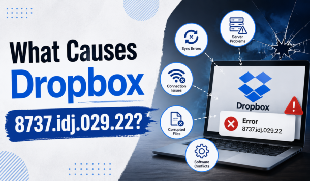
There is no single confirmed cause. Instead, several technical issues can trigger the error.
1. Corrupted Dropbox Cache
Dropbox stores temporary sync information in local cache folders. Over time, corrupted cache files can interfere with normal syncing operations.
2. Internet Connection Problems
A weak or unstable connection can interrupt Dropbox while it uploads or downloads files.
Even brief connection drops may trigger the error during large transfers.
3. Outdated Dropbox Application
Older versions of Dropbox may become incompatible with current server protocols.
This is especially common after major Dropbox updates.
4. Antivirus or Firewall Interference
Security software sometimes blocks Dropbox background processes by mistake.
VPNs and aggressive antivirus programs are frequent culprits.
5. Permission Issues
Dropbox needs read-and-write access to synced folders.
If operating system permissions change after updates, Dropbox may fail to access files properly.
6. Sync Conflicts
Editing the same file on multiple devices at the same time can confuse Dropbox’s syncing engine and create conflicts.
If you’re also organizing gaming files or team collaborations, you might find inspiration in this guide on Top Squad Name Ideas in MLBB – Ranked and Ready to Inspire, which helps streamline identity and structure for competitive play.
How to Fix Problems With Dropbox 8737.idj.029.22
Now let’s get into the fixes that actually work.
Fix 1: Restart Dropbox Properly
Sometimes the issue is temporary.
A full restart clears stuck background processes and refreshes the sync engine.
On Windows:
- Right-click the Dropbox icon in the taskbar.
- Select Quit Dropbox.
- Open Task Manager.
- End remaining Dropbox processes.
- Restart Dropbox.
On Mac:
- Click the Dropbox icon.
- Select Quit.
- Open Activity Monitor.
- Force close Dropbox processes.
- Relaunch the app.
Fix 2: Check Your Internet Connection
Dropbox relies heavily on connection stability.
Try these quick checks:
- Restart your router
- Switch from Wi-Fi to Ethernet
- Disable VPN temporarily
- Test internet speed
- Move closer to your router
- Avoid public networks during large uploads
Many users solve the issue simply by stabilizing their connection.
Fix 3: Clear Dropbox Cache
This is one of the most effective fixes.
Steps:
- Quit Dropbox completely.
- Open your Dropbox folder.
- Locate .dropbox.cache
- Delete files inside the cache folder.
- Restart Dropbox.
Do not worry — clearing cache does not delete your cloud files.
Fix 4: Update Dropbox
Running outdated software often creates compatibility issues.
To update:
- Open Dropbox.
- Go to settings/profile.
- Check for updates.
- Install the newest version.
You can also download the latest installer directly from Dropbox’s official website.
Fix 5: Disable Antivirus Temporarily
Security tools may mistakenly block Dropbox syncing.
Temporarily disable:
- Antivirus
- Firewall
- VPN software
If Dropbox starts working normally afterward, add Dropbox to your software whitelist or exclusions list.
Fix 6: Resolve File Conflicts
If multiple people edit the same file simultaneously, Dropbox may fail to sync correctly.
To fix this:
- Rename duplicate files
- Remove conflicted copies
- Keep one master version
- Avoid editing the same file from multiple devices simultaneously
Shared team folders are especially vulnerable to sync conflicts.
Interestingly, much like how users look for quick fixes or hidden insights in issues like Dropbox 8737.idj.029.22, gamers often search for updated Chainsaw Man Devil’s Heart Codes to unlock in-game advantages without unnecessary friction.
Fix 7: Reinstall Dropbox
If nothing else works, reinstalling the application can repair broken installation files.
Before reinstalling:
- Ensure your files are synced online
- Back up important local files
Then:
- Uninstall Dropbox
- Restart your computer
- Download the latest version
- Install and sign back in
In most cases, Dropbox automatically reconnects your cloud files afterward.
Is Dropbox 8737.idj.029.22 a Scam?
This is where things get important.
Several tech experts warn that fake “Dropbox error” popups are sometimes used in scam attempts. Legitimate Dropbox errors normally appear only inside the official Dropbox app or Dropbox website.
Be cautious if:
- A browser popup displays the error
- A random website asks you to call support
- You receive suspicious emails mentioning the code
- A message demands payment or remote access
If the error appears outside official Dropbox software, treat it carefully and run a malware scan immediately.
How to Prevent Dropbox Errors in the Future
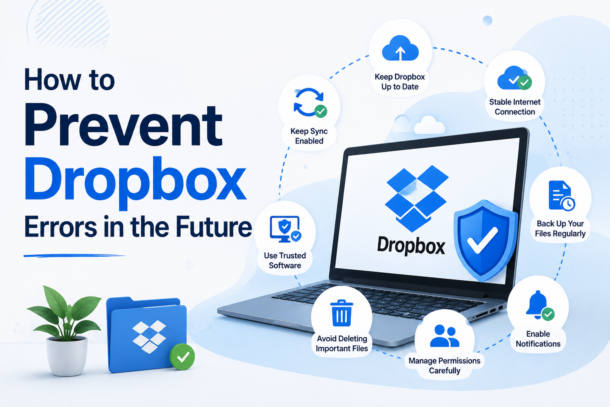
Once you fix the issue, these habits can help prevent it from returning:
- Keep Dropbox updated
- Maintain stable internet during uploads
- Clear cache occasionally
- Avoid simultaneous file editing
- Exclude Dropbox from antivirus scanning
- Use proper file naming conventions
- Restart Dropbox after major system updates
Small maintenance habits make a huge difference over time.
Much like how choosing the right setup early on matters—as seen in Fallout 4 Best Starting Stats: Optimal SPECIAL Setups For Early-Game Builds—getting your Dropbox configuration right from the start can prevent many of these issues from surfacing later.
Final Thoughts
So you have gotten “problems with Dropbox 8737.idj.029.22”? and can’t sync your latest files any more? Fear not for your files, as this is quite a common problem and rarely is associated with any data loss. Typical reasons for such problems are cached data, connection problems, outdated dropbox clients or permission problems.
For most issues with Dropbox we recommend a simple drop and drag of the dropdown menu to reset Dropbox, a delete of the cache and settings file, an update of the Dropbox application, or an uninstall and reinstall of the Dropbox application. But don’t worry! Most importantly, your cloud files are typically safe and accessible from the Dropbox website until we get you sorted out.

Virtual reality (VR) is rapidly emerging as a transformative tool in the field of rehabilitation, offering immersive, interactive, and safe environments that enhance motor learning, cognitive function, and pain management. By creating a controlled virtual space, VR enables patients to engage in repetitive, task-specific training, which is particularly beneficial for stroke survivors and individuals with neurological conditions. This innovative approach not only promotes neuroplasticity but also significantly improves mobility, balance, and engagement, allowing patients to practice daily life skills in a supportive environment.
Key Applications of VR in Rehabilitation
Physical and Motor Rehabilitation
One of the primary roles of VR in rehabilitation is its application in physical and motor rehabilitation. Research has shown that VR can improve gait speed, balance, and posture, making it particularly useful for patients recovering from strokes, Parkinson’s disease, and musculoskeletal injuries. The technology facilitates repetitive training, which is essential for enhancing neuroplasticity and functional recovery. According to a study by the National Institutes of Health (NIH), patients engaging in VR-based rehabilitation have demonstrated improvements that persist for up to 12 weeks post-therapy. This highlights the long-term benefits of integrating VR into rehabilitation programmes.
Cognitive Rehabilitation
VR is also proving effective in cognitive rehabilitation, particularly for patients with Mild Cognitive Impairment (MCI). Through simulated daily living tasks, VR enhances cognitive functions such as attention, memory, and executive function. This immersive experience allows patients to practice decision-making and problem-solving in a risk-free environment, fostering cognitive resilience and independence.
Pain Management and Psychological Health
The immersive nature of VR serves as a powerful distraction tool for pain management, particularly for patients suffering from conditions like phantom limb pain. By engaging patients in a captivating virtual environment, VR can help reduce anxiety, depression, and feelings of isolation. This is especially important for individuals undergoing rehabilitation, as mental health significantly impacts recovery outcomes.
Enhanced Engagement and Motivation
Traditional rehabilitation exercises can often become monotonous, leading to decreased patient motivation and adherence to therapy. VR transforms these repetitive tasks into engaging games, making the rehabilitation process more enjoyable. This increase in motivation encourages patients to participate actively in their recovery, ultimately leading to better outcomes.
Safe and Customisable Environments
One of the significant advantages of VR is its ability to provide a safe space for practice. Patients can engage in rehabilitation exercises without the risk of falling or injury, which is particularly beneficial for those with mobility issues. Additionally, therapists can customise the difficulty level of tasks to suit individual patient needs, ensuring a tailored approach to rehabilitation.
Telemedicine and Remote Care
As healthcare increasingly shifts towards remote solutions, VR has the potential to facilitate telemedicine and remote rehabilitation. This is particularly valuable for patients with limited mobility or those living in geographically isolated areas. By enabling therapeutic interventions to be delivered remotely, VR can make rehabilitation more accessible and convenient for a broader range of patients.
Addressing Mobility Issues
While VR holds great promise for rehabilitation, it is essential to address the specific challenges faced by individuals recovering from substance abuse, such as ketamine addiction or alcohol abuse. Substance abuse can lead to significant mobility issues, as chronic use may result in neurological impairments, muscle weakness, and coordination problems. For instance, individuals recovering from alcohol abuse may experience difficulties in balance and motor skills, which can hinder their rehabilitation efforts.
Incorporating VR into the rehabilitation process for these individuals can provide a unique advantage. The immersive nature of VR allows patients to engage in physical activities that may otherwise be challenging due to their condition. By creating scenarios that simulate real-life situations, VR can help patients practice essential motor skills and regain confidence in their physical abilities. Furthermore, the engaging aspect of VR can motivate individuals to participate in their recovery actively, reducing the risk of relapse and encouraging a healthier lifestyle.
Challenges and Future Outlook
Despite its many benefits, the implementation of VR in rehabilitation is not without challenges. Technical limitations, such as high costs and the requirement for substantial data bandwidth, can hinder widespread adoption. Additionally, some patients may experience discomfort or dizziness when using VR, which necessitates further research and development to enhance user experience.
Moreover, there is a need for improved motion tracking for fine motor tasks and rigorous clinical validation of VR applications in rehabilitation. As researchers continue to explore the potential of VR, it is crucial to address these challenges to ensure that this innovative technology can be effectively integrated into rehabilitation programmes.
In conclusion, virtual reality is rapidly changing the landscape of rehabilitation, offering a powerful, engaging, and effective tool that complements traditional therapy methods. By enhancing motor learning, cognitive function, and pain management, VR has the potential to significantly improve recovery outcomes for patients. As the technology continues to evolve, it is essential to embrace its capabilities and address the challenges it presents, paving the way for a more effective and accessible rehabilitation experience for all.

When you first come across the phrase “what cilfqtacmitd help with,” you might think it’s some complicated jargon or a technical code. The good news? It isn’t meant to confuse. In fact, understanding what cilfqtacmitd help with can unlock real practical value — especially if you’re dealing with accounting, finance, or managing foreign currency transactions in your business.
In this article, we’ll untangle the concept, explain it in plain language, and walk you through who can benefit from it and how. Let’s dive in.
What Is Cilfqtacmitd?
At its core, the term “cilfqtacmitd” refers to an accounting mechanism used to track differences arising from foreign currency transactions — particularly with long-term monetary items. If your business engages with foreign currency loans, investments, or receivables that aren’t settled immediately, currency rates can fluctuate between when the transaction was recorded and when it’s settled.
Those differences in exchange value need to be accounted for in your financial statements, and that’s where mechanisms like cilfqtacmitd come in.
To understand what cilfqtacmitd help with, it’s helpful to think of it as a tool within accounting used to:
- Capture changes in foreign exchange values over time
- Amortize exchange gains or losses over the life of the long-term item
- Provide consistency and transparency in financial reporting
This is particularly pertinent to accounting standards relating to foreign currency transactions, where it is specified that where long-term foreign currency monetary items vary due to changes in value caused by fluctuations in exchange rates, accounting for these differences should be done systematically rather than in bulk.
Why Does Currency Translation Matter?
Imagine your company took a loan in US dollars, but your books are in Indian rupees. When you initially recorded the loan, the dollar might have been worth a certain amount. Months or years later, that dollar value changes — sometimes significantly.
This difference isn’t just abstract numbers on paper — it can affect your:
- Balance sheet figures (assets or liabilities)
- Profit and loss statements
- Future cash flow expectations
Instead of ignoring these differences or booking them all at once, cilfqtacmitd provides a systematic way to handle them over time, which smooths financial results and offers a more accurate picture of your company’s financial health.
Meanwhile, iOS App eTrueSports: Features, Guide & How to Use offers a closer look at functionality, setup, and practical usage in a structured format.
So, What Cilfqtacmitd Helps With — Explained
In simple terms, cilfqtacmitd helps with:
1. Tracking Currency Impact on Long-Term Monetary Items
When exchange rates change between the date of a foreign currency transaction and the date the item is settled or reported, the value changes. Cilfqtacmitd captures these differences rather than letting them skew a single accounting period.
2. Amortizing Exchange Gains or Losses
Rather than taking into account all the gains or losses in one go, which might affect the profit situation, the same can be averaged out during the longevity of the particular asset or liability.
3. Enhanced Accuracy in Financial Reporting
The financial statements represent only the true picture of the going concern activities and performance when the differences in translation are treated separately, and not all of these items are included in the profit/loss account.
4. Supporting Compliance with Accounting Standards
Various accounting frameworks require that exchange differences on monetary items be reported systematically — and cilfqtacmitd is one of the tools that help companies meet those requirements.
Who Should Care About What Cilfqtacmitd Help With?

Not every business needs to wrestle with foreign currency accounting. But if your operation meets any of the following conditions, you’ll want to understand what cilfqtacmitd help with:
International Business Owners
If you import, export, borrow, or lend across borders and the funds aren’t settled immediately, exchange rates will affect your books.
Finance & Accounting Professionals
Managing exchange differences accurately is essential for auditors, accountants, and CFOs. Understanding how cilfqtacmitd works makes compliance and reporting smoother.
Investors and Financial Analysts
If you analyze companies with global exposure, knowing whether and how they handle currency translation differences helps you see the real financial picture.
Students of Accounting or Finance
This concept often appears in advanced accounting courses, especially those covering foreign exchange and monetary items under standards like AS 11.
For a deeper look at potential concerns, Why Zixyurevay Harmful: Understanding the Risks outlines key factors worth being aware of.
How Cilfqtacmitd Is Applied in Practice
Let’s walk through a basic example to ground the idea:
Your Company Borrows $100,000:
At the time of the loan, the exchange rate is USD/INR = 75, so you record ₹75,00,000.
A Year Later, Exchange Rate Shifts:
Now USD/INR = 80. If you were to settle the loan today, it’d be ₹80,00,000 — that’s a ₹5,00,000 difference.
What do you do with that ₹5,00,000? Instead of dumping it all into one year’s profit or loss, you use cilfqtacmitd to accumulate and, if appropriate, amortize it over the period the liability exists. This spreads the impact instead of rocking one year’s results.
Real-World Application: When It’s Most Effective
Here’s where cilfqtacmitd really shines:
Long-Term Foreign Borrowings
Exchange rate changes on loans — especially those lasting several years — can create big after-tax swings that cilfqtacmitd helps manage.
Foreign Currency Receivables & Payables
When you’re owed money or owe money in another currency over time, currency movements matter.
Capital Expenditures With Foreign Funding
Buying equipment using foreign currency often involves deferred payments. Translation differences over the life of that asset are captured systematically.
Hedging and Risk Management
When companies use financial instruments to protect themselves against currency risks, transparency around translation differences supports better reporting.
Tips for Implementing Cilfqtacmitd the Right Way

If you’re going to use this system, here are a few practical pointers:
Maintain Clear Records:
Track exchange rates on transaction dates and reporting dates.
Consistency Is Key:
Apply the same method across reporting periods.
Coordinate With Auditors:
External auditors will want transparency on how and why you amortize differences.
Use Accounting Software:
Many modern systems support foreign currency tracking and can automate parts of the process.
You might also come across Is Fidzholikohixy Safe? A Comprehensive Analysis, which takes a closer look at its overall safety and reliability.
Common Misconceptions
Let’s clear up a few things people often get wrong about what cilfqtacmitd help with:
It’s Not Just for Big Companies
Even small companies with occasional foreign dealings can encounter currency differences.
It Doesn’t Eliminate Risk
It helps with reporting and smoothing results — but it doesn’t remove the economic impact of exchange rate movements.
It’s Not Optional If Standards Require It
In jurisdictions following certain accounting standards, you must systematically account for effects of exchange rate changes — and cilfqtacmitd is part of meeting those requirements.
Final Thoughts: Why It Matters
Understanding what cilfqtacmitd help with isn’t just about decoding a strange word. It’s about appreciating the logic behind good financial reporting in a global economy. Exchange rates change. Currencies fluctuate. When companies respond to that reality thoughtfully, their financial health looks clearer — both to internal decision-makers and external stakeholders.
If your business touches global markets, or if you’re involved in accounting or finance, this concept will make your financial discussions richer and your reports more accurate.
-
 Guides6 years ago
6 Proven Ways to Get more Instagram Likes on your Business Account
-
Mainstream11 years ago
BioWare: Mass Effect 4 to Benefit From Dropping Last-Gen, Will Not Share Template With Dragon Age: Inquisition
-
 Mainstream8 years ago
How to Buy Property & Safe Houses in GTA 5 (Grand Theft Auto 5)
-

 Guides2 years ago
Free Fire vs PUBG: Comparing Graphics, Gameplay, and More
-

 Guides1 year ago
50+ Free Fire ID and Passwords Login List (Giveaway) 2025
-
 Casual3 years ago
8 Ways to Fix Over-Extrusion and Under-Extrusion in 3D Printing
-

 Other2 years ago
Ajjubhai UID: Free Fire Details & Earnings
-

 Features2 years ago
Exploring Valorant eSports Stats: Unveiling the Metrics Behind Competitive Excellence